Mars Pathfinder Rover
Vehicle Software Design Document
MARS ROVER DFM-96-016
Updated 9/9/96
Prepared by:
Jack Morrison
Tam Nguyen
Andrew Mishkin
CONTENTS
1. SCOPE AND PURPOSE
The Mars Pathfinder Microrover Flight Experiment (the "rover") will
perform engineering and science experiments on the Martian surface to
pave the way for future Mars missions.
This document
describes the high level design of the rover's on-board software.
2. APPLICABLE DOCUMENTS
- 2.1 "Microrover Flight Experiment Requirements, Architecture, and Verification Document", Version 5.1, July 16, 1993.
- 2.2 W.E. Layman and J.R. Matijevic, "Micro-Rover Reference Design: Highlights and Design Philosophy", RVDFM 93-006T.
- 2.3 A. Mishkin, "Microrover Vehicle Software Requirements Document", RVDFM 94-019 (Rev. A), February 23, 1994.
- 2.4 B. Cooper, "Rover Control Workstation Functional Requirements Document", RVDFM 94-025 (Rev. A), March 4, 1994.
- 2.5 "Electronics Hardware Design Document", RVDFM 93-XXX
- 2.6 "Rover/Lander Communication ICD", IOM 3472-93-064
- 2.7 "Alpha Proton X-ray Spectrometer Electrical and Control Interface and Control Document", RVDFM 94-042
- 2.8 "LeRC Materials Adherence Experiment ICD", RVDFM 93-039
- 2.9 "LeRC Wheel Abrasion Experiment ICD", RVDFM 93-048
- 2.10 T. Nguyen, "Image Data Compression Using BTC on the 8085 Processor", RVDFM 93-032
- 2.11 "Goto XY Strawman Algorithm"
- 2.12 "Sinkage and Slippage Estimation for a Mars Microrover"
- 2.13 J. Morrison and T. Nguyen, "Mars Pathfinder Rover Command Dictionary", RVDFM 94-032.
- 2.14 J. Morrison and T. Nguyen, "Mars Pathfinder Rover Telemetry Dictionary", RVDFM 94-033.
3. SOFTWARE DESIGN
3.1 General Approach
3.1.1 Design Criteria
The rover will be operating in a harsh and mostly unknown environment,
with limited electrical and processing power, accessible only via a
limited-bandwidth communication link with long time delays. The
software design is driven by these factors to provide:
- Reliability - handling failures of non-essential
hardware components and unexpected environmental conditions.
Time-critical anomalies (e.g. power drains and unexpected obstacle
contact) must be handled autonomously. Software failures must be
protected against occurring, and recovered from if they do occur.
- Flexibility - adapting to changes in the rover's hardware
and environment. Modifications to behaviors should be autonomous or
easily commandable. Where possible, the rover should be
self-calibrating (automatic or commandable).
- Simplicity - In general, the simplest acceptable approach
to each requirement is chosen. Besides being more reliable and
flexible, simpler solutions are easier to test and have more
predictable behavior. (This is also dictated by the high-level
requirement to stay within a limited budget.)
- Visibility - concisely but completely reporting the
current hardware and software state, in particular anomalous
conditions.
Some of the functionality in this document is labeled as "extra
credit", meaning it will be implemented at lower priority if
development time and processing resources allow.
3.1.2 Hardware Environment
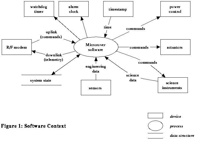
Reference 2.5 describes the rover computer and I/O subsystems. Figure
1 summarizes the interfaces to the rover software.
3.1.3 Software Structure
The rover software consists of a single-threaded control loop, with
interrupt handling only for exception conditions (contact sensor,
power loadshed, and timeout alarms). The limited processing and
electrical power available make a multitasking executive
inappropriate, as do the deterministic timing requirements of the
direct CCD interface.
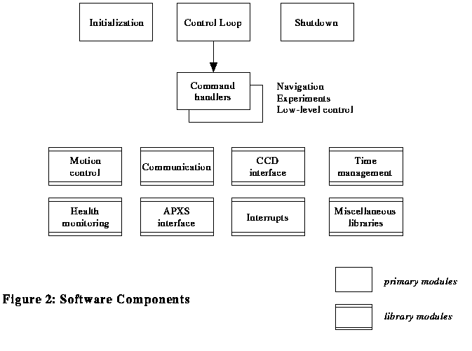
The major software components are shown in Figure 2, and consist
primarily of a top-level control loop, a set of command
handlers, and libraries of support functions.
The control loop performs periodic functions, requests command
sequence uplinks, and dispatches commands to the appropriate handlers.
Command handlers have several responsibilities:
- validate the request, including checking for the availability
of required devices, and sufficient power
- power on devices as needed, and power them off when done
- monitor termination conditions, including time-outs
- collect sensor data
- generate telemetry, including normal results and/or error reports
- periodically update the watchdog timer and software clock
Command handlers return control to the control loop upon completion of the command.
Library functions are organized into hierarchical layers of capability
to support the command handlers and control loop. For example, the
waypoint traverse proximity sensing module and the imaging command
handler both use the CCD interface module, which in turn uses the
low-level I/O module to control the hardware.
3.1.4 Vehicle State Information
A global data structure records the current state of the rover, including:
- Mission phase (pre-launch, cruise, pre-release, pre-deploy, normal surface operation, extended mission)
- Vehicle position and orientation (X, Y, heading in lander coordinates)
- Driving state (stopped, forward, reverse, turning)
- Contact sensor indicators
- Loadshed indicator
- Total odometry counters (average + one per wheel)
- Lost communication indicators:
- lost lander comm: telemetry buffering
- lost earth comm: contingency state
- Last reading for each analog sensor
- Failure count for each device (sensor, actuator, power unit, etc.)
- Expected wakeup time
- Time of last earth command
- Communication error counts (modem, APXS)
- Control parameters
- Current error state
- Error state mask
- Contingency sequence pointer
- Motor (pot) positions
This structure is divided into volatile and non-volatile parts; a copy
of the non-volatile part is updated in EEPROM at every heartbeat
during traverses, after the execution of any command that changes the
state, and before shutting down power.
The lander coordinate system ("fixed level frame") is defined in reference 2.4.
The rover coordinate system is a right-handed, orthogonal, Cartesian
frame with its origin at the center of the rectangular plane defined
by the four corner wheel centers (when the rover is level). Positive
Z is perpendicular to this rectangular plane, pointing down. Positive
X coincides with the forward traversal direction. Positive Y is to the
rover's right (see Figure 3).

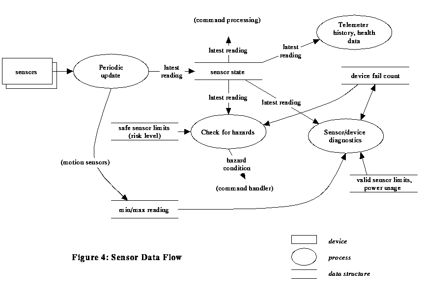
The device failure counts are incremented each time the health
check function detects an apparent problem with the associated device,
and decremented when the health check determines that it's working
properly. They are used to determine whether the corresponding sensor
reading is "trusted" (e.g. whether an out-of-range reading is cause
for aborting an operation, or whether an alternate sensing procedure
should be used if possible). Figure 4 shows how sensor data is
handled. If an actuator has failed, the rover doesn't use it. The
operator can override this by forcing specific devices into a failed
or valid state by command - this allows disabling of devices,
including the watchdog timer, and tracking of "spent" one-shot devices
(such as the APXS failsafe). The failure count for devices flagged as
failed (but not forced failed by command) is decremented once at cold
start (morning wakeup) for a "second chance". Failure counts are also
used to mark devices that are not to be turned on at all (e.g.,
shorted), and to indicate devices that are unusable if the 12v analog
power supply has failed.
There are several related but distinct "timeouts" associated with
rover operation, including:
- command execution timeout - a short-term limit on the
completion of the current command, enforced both in software and with
the alarm clock hardware, resulting in termination of the command
- lander communication timeout - a short-term limit
(seconds) on waiting for valid communication with the lander. After a
limited number of retries, "loss of lander communications" is
indicated (possibly due to the lander being unavailable [e.g. at
night], extended mission operation out of lander comm range, or a
hardware failure). This results in buffering of telemetry data,
unless or until contingency operations are started.
- earth communication timeout - a long-term limit
(hours) on waiting for a valid command upload. Expiration of this
timeout initiates contingency operations.
The control parameters are a list of flags, thresholds,
calibration factors, etc. that affect the behavior of the software,
but don't need unique commands to modify them (i.e. don't require
special processing when changed). On the other hand, a more
convenient access method than patching is appropriate, so a SET
PARAMETER command is provided to update these parameter values. The
parameters are defined in the Command Dictionary, reference 2.13.
Some particular ones are referred to in this design document:
- {RISK_LEVEL} - indicates the amount of risk the rover
is willing to accept, by adjusting safety limits and thresholds
- {BATT_USAGE} - determines the functions for which the rover is allowed to use battery power
Note: Values and behaviors that are adjusted by control parameters are indicated in this document with the notation {name}, where name is the parameter name in the Command Dictionary.
3.1.5 Error Handling and Reporting
The rover maintains a set of error state flags, cleared during startup and set when the corresponding conditions occur during command execution. The flags are:
- Command execution time-out - command was aborted due to soft time-out (not completed by expected duration), hard time-out (alarm clock safety time-out), or watchdog reset.
- Device failure - a previously working device (sensor, actuator, power converter, etc.) failed.
- Device not available - a device critical to completion of the command was (already) marked as "failed".
- Nontraversable hazard encountered - a navigational hazard was detected by proximity, articulation, acceleration, contact, power, sink-slip, etc. sensing, or heartbeat failure, which the rover was unable (or unwilling at the current {HAZ_AVOID} settings) to get around.
- Insufficient power - solar power is not sufficient to perform a requested operation (and {BATT_USAGE} is not enabled for the needed devices).
- Overtemperature - the warm electronics box is at or above the maximum allowed {WEB_LIMIT} temperature; command was ignored (since powering on the devices needed to perform the command might have overheated the WEB).
- Invalid command - command code or parameters are invalid, or the sequence is rejected due to overflow.
- General command failure - command completed unsuccessfully (command-dependent failure)
Most commands are skipped if any error flags are set, unless those flags are masked by corresponding error mask bits. Commands are provided to set the error mask, and to clear the error flags (these latter commands, along with "end of sequence", "abort", and "shutdown" commands, are performed regardless of the error state). Skipped commands generate "command acknowledge" telemetry messages indicating that fact.
"Command execution results" telemetry messages (for those commands that generate them) contain a field indicating the error flag values before and after execution of the command.
When the software detects an anomalous condition, it sets appropriate error state flags, and calls an error logging function, passing error information and a severity level (0 = minor, 1 = major, 2 = critical). If the level is at or above the current error reporting threshold {EREP_LEVEL}, the error is noted in a timestamped error message. Any such messages accumulated during execution of a command are sent in a "critical state" error telemetry packet, separate from any normal command telemetry, at the completion of the command.
3.1.6 Arithmetic Standards
Due to the limited capability of the rover CPU, no floating point arithmetic is used. Where necessary, calculations are performed in an appropriate fixed-point notation.
Angles are represented using 16-bit Binary Angle Measurements (BAMs), where 2**16 BAMs = 1 revolution (1 BAM = 0.0055 degrees).
Distances are measured in millimeters.
Time is maintained as a 5-byte binary counter with 4 bytes of "coarse time" (CCSDS time in seconds) and 1 byte of "fine time" (units of 1/256 sec = 3.9 msec = 1 "centon"). Standard subsets of this counter are defined (byte 0 = least significant, byte 4 = most significant):
| name | # bits | bytes used | approximate range |
|---|
| Full time | 40 | 0 - 4 | 4 msec to 136 years |
| Long seconds | 32 | 1 - 4 | 1 sec to 136 years |
| Long centons | 32 | 0 - 3 | 4 msec to 194 days |
| Short seconds | 16 | 1 - 2 | 1 sec to 18 hours |
| Short centons | 16 | 0 - 1 | 4 msec to 4 minutes |
Note that seconds (as well as minutes, hours, etc.) are always "Earth seconds" or "atomic seconds", as opposed to "Mars seconds".
3.2 Components
3.2.1 Initialization
The rover software starts execution from a reset vector when the CPU is reset. This occurs when sufficient power becomes available from the solar panels, or when battery power is switched on by the alarm clock or lander-controlled wakeup switch, or when a watchdog time-out occurs. The reset handler checks for a GSE debug connection; if active, it invokes a debug monitor. It then checks for valid EEPROM contents (where the main rover software is stored); if valid, the main software initialization is invoked. It EEPROM is not valid, a limited rover control program in PROM is started instead. The main initialization
function sets up the software and hardware environment, determines the appropriate mission phase, and invokes the main control loop.
The rover distinguishes between a "warm start" (time-out reset or hard device failure) or "cold start" (powerup) by checking a RAM location for a special pattern (stored at the end of initialization code) that should not occur in uninitialized memory. (RAM contents are not used during a warm start except as telemetry data - everything is reinitialized from nonvolatile memory, in case a power glitch left the warm start pattern intact but other locations altered.) Activation of the watchdog and command execution timer is disabled if the devices are marked as failed; the rover automatically marks them as failed (until commanded otherwise) if several consecutive premature time-out resets occur.
	save selected RAM data in case of warmstart
	load persistent state data from EEPROM
	enable loadshed interrupt handling
	turn on CCPS power switch
	initialize power control, turning on 12V converted for analog I/O
	wait until enough power to keep 12V on without loadshed
	determine wakeup cause
	if alarm clock or watchdog timeout
		report timeout error
	if apparent power reset
		report device error
	if coldstart wakeup (alarm clock, solar, or lander)
		decrement failure counts of soft-failed devices
	initialize timer handling
	initialize telemetry packet handling
	if APXS was left on (night mode)
		suspend APXS data collection
		turn off APXS
	if solar wakeup and {batt_usage} doesn't allow batteries for 12V
		turn off CCPS
	wait until enough power to keep 12V and modem transmit on
		without loadshed
	check for automatic mission phase change based on gravity
	if on Mars
		close 3BSS switch to bring all batteries on-line
	if coldstart
		heat modem for {MODEM_HEAT} seconds
	perform clock sync communication with lander
	if unexpected warmstart and possibly valid telemetry data left in RAM
		send telemetry data
	perform {HEALTH_LEVEL} health check
	start control loop
3.2.2 Control Loop
The main control loop checks for and dispatches uplink command sequences. In between (and while waiting for) commands, it monitors periodic tasks, including thermal management, loadshed alarm recovery, automatic health checks, and automatic end-of-day
shutdown. The control loop also collects data for the sequence execution report telemetry message sent at the end of each command sequence.
When a command sequence is received by the rover, it is immediately parsed and validated. If any errors are found, the sequence is rejected (on the chance that it was corrupted during transfer from the lander) and re-requested. If still invalid after retrying, the sequence is acknowledged (so that the lander can release it) and valid commands in the sequence are processed. If an invalid command is found during execution (either uncorrected by retries, or invalid by execution-time context), the "invalid command" error flag is set and that command is aborted.
In between command execution (and periodically during wait command execution {CMD_RATE}), the rover checks for a pending command sequence on the lander. If one is present and starts with an Abort command, the rover shuts off all actuators, discards the remainder of the current command sequence, and uploads the new sequence; otherwise, it rejects the new sequence so that the lander will keep it until the rover is ready for it.
Whenever a valid command upload, or a "no commands available" response, is received from the lander, the rover resets its "loss of lander communication" indicator. If it has telemetry data buffered in RAM or EEPROM, it sends the buffered data to the lander and resets telemetry buffering. Receipt of a valid upload resets the "loss of earth comm" indicator (canceling contingency operations if active) and resets the earth communication timeout.
3.2.3 Shutdown
The rover shutdown process is performed:
- when commanded
- when no pending commands are available and the solar panel (but
not the alarm clock) has failed
- in between commands if the solar panel is operational, the local
time-of-day is past a threshold {END_OF_DAY}, and the solar
panel voltage is lower than a threshold {SHUTDOWN_POWER}.
The threshold parameters can be altered to allow
night operations.
The alarm clock is set to power the rover back up at an appropriate wakeup time (the commanded time, or the {DEFAULT_WAKEUP} time-of-day). If the APXS is active, data collection is stopped. If night mode collection has been enabled (by {APXS_NIGHT}), the APXS night-mode relay is latched to connect the APXS directly to the battery bus and colection started/continued. Vehicle state information is stored in EEPROM, along with any remaining commands in the current sequence. Batteries are disconnected from the core bus. The processor is placed in an idle loop with interrupts disabled (and the watchdog timer kept reset) to stay in a safe state until solar power drops below the power monitor threshold.
A shutdown command with a wakeup time of zero requests a system reset (warmstart). The rover accomplishes this by forcing a watchdog timeout.
3.2.4 Vehicle Control/Navigation
3.2.4.1 Navigation Modes
A fundamental capability of the rover is to drive around. The software provides several driving modes:
- Waypoint navigation: semi-autonomous driving to a
designated destination position
- Rock-finding: semi-autonomous driving in search of a
rock
- Direct move (including deploy from lander): direct driving
for a specified number of encoder counts
- Turn in place: changing heading without changing X/Y
position.
- APXS-positioning: direct (backwards) driving until
APXS sensor is in contact with rock
- Unstow: driving of rear wheels to raise rover from stowed
to operational configuration
All modes include:
- Dead reckoning/odometry to maintain vehicle position and heading information
- Monitoring of sensors for hazard conditions (contact, articulation, attitude, power, thermal)
- Monitoring of motor currents for overheating
- Time limit on execution
- Logging and telemetry of traverse data (engineering history)
The primary distinction between the driving modes is the criteria for declaring completion. The waypoint navigation and rock-finding modes also include:
- Periodic heartbeats to verify communication with lander
- Proximity detection of hazards by laser/CCD scanning
- Turn/backup behaviors to avoid hazards
3.2.4.2 Waypoint Navigation
This is the normal traverse mode, driving to an operator-designated point
while avoiding obstacles. The vehicle travels in small steps (high-rate loop), stopping frequently (due to power limitations) to perform proximity detection and hazard assessment. If a hazard is detected in front of the rover, it turns away from the hazard
direction in steps, repeating the proximity scanning until a clear path is found. The vehicle continues on this "avoidance heading" for a short distance, then steers back toward the original destination. Detected hazard conditions are noted in flags in a global hazard state indicator.
	steer wheels straight
	do navigation_startup
	start drive motors (all forward)
	loop until at destination or untraversable hazard:
		high_rate loop (until at next stop point):
			do drive_update
			check distance to goal
			do navigation_check
		end
		stop wheels
		if time for heartbeat
			do heartbeat communication
		do hazard_avoidance
		adjust steering toward goal (or along
				avoidance heading) (Figure 6)
		restart drive motors
	end
	do navigation_stop
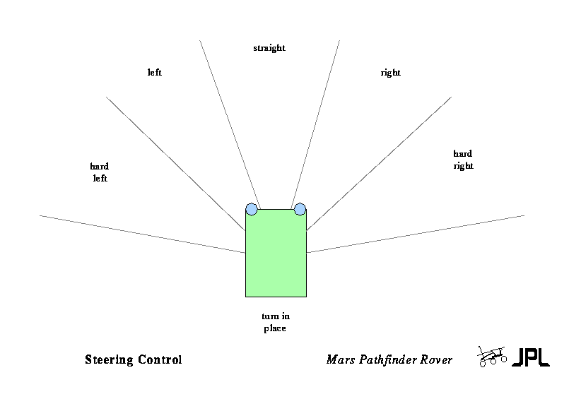
Figure 6
3.2.4.3 Rock-Finding Navigation
This mode starts by driving toward a specified destination, as in waypoint navigation. However, a rock-like obstacle results in completion rather than avoidance. If the waypoint is reached without finding a rock, or a non-rock obstacle is encountered, the rover starts a roughly spiral search pattern. Note that this is not a search for a specific rock, nor a dead-reckoning correction capability.
The logic is the same as for waypoint navigation, except for adjusting the "destination" for the search pattern, and centering the rover heading between the edges of the rock (using proximity sensing) at completion.
3.2.4.4 Direct Move Navigation
In this mode, the vehicle drives continuously at specified steering angles, for a distance specified as encoder counts. This is used for deployment from the lander, and as fallback low-level driving control. If all encoders have failed, the drive distance is approximated based on time.
	set time limit
	steer wheels to specified steering angles
	do navigation_startup
	start drive motors in specified direction
	loop until reached destination or hazard
		do drive_update
		do navigation_check
	end
	stop wheels
	do navigation_stop
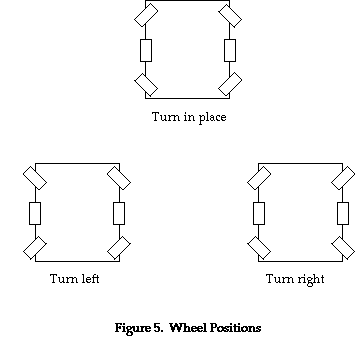
3.2.4.5 Turn In Place Navigation
In this mode, the vehicle spins about its center to change heading. This can be performed on command, or as a step during the waypoint and rock-finding navigation modes. (Odometry or time-based control can be used as a backup if the heading sensor has failed.)
	set time limit
	steer wheels to turn-in-place position (Figure 5)
	do navigation_startup
	start drive motors (L & R sides in opposite direction)
		for shortest turn direction
	loop until about to cross desired heading, or hazard
		do drive_update
		do navigation_check
	end
	stop wheels
	do navigation_stop
3.2.4.6 Position APXS Navigation
In this mode, the vehicle drives straight back, monitoring contact sensors on the APXS for contact with a rock surface.
	set time limit
	steer wheels straight
	do navigation_startup
	start drive motors (all reverse)
	loop until contact, reached travel limit or hazard
		check APXS contact for done
		do drive_update
		do navigation_check
	end
	stop wheels
	do navigation_stop
3.2.4.7 Unstow (Standup/Bogey Lockup)
This command function is used to prepare for deployment from the lander. The rover first checks that the lander has released it, as indicated by the APXS contact sensors. Next, the rover drives the two rear wheels (only) to raise the vehicle from the stowed position on the lander, until the bogeys are locked (as indicated by the bogey pot sensors). It then checks for proper latching by trying to back off the rear wheels. Upon successful completion, the mission phase is changed to pre-deployment.
3.2.4.8 Navigation Support Intermediate Functions
These functions perform groups of actions common to the various
driving modes, as referenced above:
navigation_startup

	turn on and calibrate gyro
	turn on accelerometers, LEDs (encoders)
	initialize contact sensors
	record telemetry header

navigation_stop

	turn off accels, contact sensors (gyro is left on for stability)
	finish telemetry

drive_update

	scan sensors
	update dead reckoning
	update telemetry

navigation_check

	check timeout
	check loadshed
	check lander proximity hazard
	check for sensors exceeding safe limits (at the current {RISK_LEVEL})
	check for unmasked contact
	check motor current (overheat or stall)
3.2.4.9 Hazard Avoidance
For direct driving commands, a hazard condition (see navigation_check
above) causes the traverse to be aborted, and (optionally) the capture
of images of the rover's surroundings.
For waypoint and rock finding navigation, laser/CCD obstacle proximity
detection is also performed, and the rover may be permitted to avoid
certain hazards. Proximity hazards are avoided by turning in place
until the obstacle is no longer in the way; other hazards are avoided
by first backing up and then turning away.
3.2.4.10 Low-Level Navigation Support
- Sensing
During navigation, the rover monitors it sensors in order to collect
engineering history data and to check for hazards.
Sensor data is recorded for telemetry every 2 seconds. If the
{TELEM_RATE} parameter is set greater than one (to reduce telemetry
volume), sensor data is recorded every 2 seconds into a fixed-size
FIFO buffer (sized to hold at least 1 minute's worth of data), but
only every Nth sample "pushed out" of the FIFO (when making room for
new data, or when flushing the FIFO at completion) is transmitted. If
the traverse is aborted (due to timeout, non-traversable hazard,
etc.), the entire contents of the FIFO are sent. The sensor data
supports sensor performance, terrain characterization, vehicle
performance, and wheel abrasion experiments.
Normally, power to the linear accelerometers is left on during
driving. The parameter {POWER_SAVE} can enable "power-saving" mode,
where the devices are powered on only when the vehicle is stopped (at
each traverse cycle). This leaves more power for the drive motors, in
exchange for added risk of power cycle stress to the components.
- Dead reckoning
During the traverse, the average counts from the wheel motor encoders
are accumulated in a move or turn odometer, depending on the rover
traversal mode. The move odometer accumulates forward traversal
distances, while the turn odometer accumulates motion during
turn-in-place maneuvers (as a backup for the turn rate sensor in the
event of rate sensor failure). Separate odometer accumulators are also
kept for each wheel for telemetry.
The current X/Y position is updated periodically during traverse using the equations:
- distance = odometer_change * scale_factor * cos(tilt)
- new x = old x + distance * cos(heading)
- new y = old y + distance * sin(heading)
The scale factor (encoder counts to millimeters) is settable parameter
{MM_PER_COUNT} to allow compensation for estimated wheel slip (extra
credit: adjust scale factor based on vehicle pitch to account for
non-flat terrain).
- Motion control
These functions control all the motors and associated sensors to perform coordinated vehicle movement.
When starting more than one motor, the software waits 50 msec between
turning on each motor to limit peak power use, staggering left and
right sides.
During motor usage (e.g. driving), the rover calls a periodic motor
monitoring function at least once per second. This function tracks
total motor current for the last 32 seconds to estimate the loading
for each motor.
If the total current exceeds {MOTOR_LIMIT} threshold, all motors are
stopped and the current operation suspended for 300 seconds
{MOTOR_COOL} to prevent overheating. Timeout monitoring continues
during this suspension interval. Motor current above the higher
threshold {STALL_CURRENT} for several consecutive samples results in a
motor stall hazard alarm.
Steering motor control uses the pot sensors for feedback, adjusting
one to four wheels at the same time. The APXS deployment motor is also
controlled using a pot position sensor.
If the pot sensors fail, a backup steering and APXS motor control
method is to store the current position, and adjust position by
driving the motor for an appropriate length of time. Position and slew
rate can be recalibrated on command by driving a motor until its
current draw goes above a threshold, indicating the limit of travel
has been reached.
Recalibration is performed automatically when starting a drive or APXS
deploy operation.
3.2.5 Soil Mechanics
Reference 2.1 describes the soil mechanics experiment. The basic
support for this command is a function to run a specified wheel motor
for a specified number of encoder counts, while recording sensor data
for telemetry. The run can be repeated several times (with a 500 msec
pause in between) using a single command.
3.2.6 APXS Control
These functions implement commands to control the APXS and retrieve
spectrum data, according to the interface described in reference 2.7.
A typical APXS experiment requires several commands. (Design of
specific command sequences will depend on the details of the
individual experiment and operations constraints.) Example operations
include:
- drive to rock location
- find rock (center heading on rock)
- turn 180 degrees
- run APXS deployment motor to extend sensor
- position APXS (backup vehicle)
- power on APXS
- APXS command: clear memory
- APXS command: start data collection
- wait
- APXS command: stop data collection
- APXS command: reset
- APXS command: retrieve data
- power off APXS
- run APXS deployment motor to retract sensor
To position the APXS sensor against the rock, the rover drives
backwards (with all steering wheels straight) until contact is
registered on at least one APXS contact sensor, and continues to drive
for 1 second.
The rover is also capable of deploying the APXS directly onto a rock
or soil target, after the vehicle has been positioned to the desired
location, monitoring the APXS contact sensors during APXS mechanism
deployment.
The rover communicates with the APXS over a serial port, sending a
specified command byte with acknowledge sequencing. If a command
sequence is unsuccessful, it retries two more times, pausing one
second between each retry. If still unsuccessful, it cycles power on
the APXS and retries two more times before giving up.
When commanded to read spectrum data, the rover requests this data from the APXS and transmits it in telemetry packets to the lander.
A count of communications errors with the APXS (since start of mission) is included in the telemetry message.
3.2.7 Material Adherence Experiment Control
This function performs the solar cell/dust cover and QCM adherence experiments, following the steps indicated in reference 2.8 to acquire and transmit the data.
3.2.8 Wheel Abrasion Experiment Control
This function performs a wheel abrasion experiment by running the test wheel while monitoring its encoder. Every time the encoder has incremented at least 16 counts, the encoder value and WAE cell voltage are recorded. This continues for 250 samples, which are then returned in a telemetry packet as described in reference 2.9.
3.2.9 Contingency Mission
Contingency operation is initiated by the main loop if the rover receives no valid commands from the lander for {CMD_TLIM} minutes and there are no commands in the queue. The hope is that the communication loss is only in the lander-to-rover direction, or, at least, that the lander can see the rover with its cameras (thus the rover's behavior should be very predictable so that the lander cameras can be pointed where it should be). The rover continues to check for commands from the lander, but doesn't reset the {CMD_TLIM} timer unless a valid upload is received.
Predefined sequences likely to take more than one day to complete include "shutdown for the night" commands where appropriate. They are stored in specific EEPROM locations, with spare room allocated, to simplify uploading new sequences (through memory patching).
3.2.10 Miscellaneous Commands
These commands are primarily for software development support, but may be useful during the mission in the event of unexpected conditions or failures.
3.2.11 Communication
This component consists of several layers of functions supporting communication with the lander over the R/F modem link. Since the rover is in control of communication sessions, simple polled serial I/O can be used. Reference 2.6 defines the interface protocol.
Power to the modem is turned on only during communications sessions. While operating, modem current draw is monitored at least once per 700 msec to check for latchup. If the current exceeds a limit, the modem is powered off and the current session attempt aborted.
- Frame I/O
These low-level functions send and receive individual data frames, computing or checking CRC codes, and retrying transfers when errors are detected. Link performance is monitored by counting transmit and receive packets and errors. During contingency operation, receive timeouts are handled in a manner that allows telemetry to be sent without handshaking.
- Session protocol handling
These functions control the sequencing of frames making up a communication session (heartbeat, clock sync, telemetry downlink, or command uplink).
- Packet output formatting
This function constructs a telemetry packet for downlink, building CCSDS primary and secondary headers. If lander communication is unavailable (at night or extended mission out of range, but not in contingency operation), the packet is stored in bulk RAM or EEPROM (or discarded), as specified by {TBUF_MODE}. If the buffering area is full, new data is discarded (this allows, for example, the rover to go over the horizon, capture images, and not overwrite the image data during the traverse back). [extra credit: option for circular buffer to retain most recent data instead.]
A related function performs transmission of buffered telemetry (called when communication is restored).
- Telemetry data/history collection
These functions collect engineering data during command execution according to telemetry packet formats. They report when the current packet buffer is full (so that the calling function can request packet transmission).
- Session retry/modem latchup recovery
If a communication session fails, it is retried two more times. Before each retry, the modem is switched off (in case the failure was due to a modem logic upset), and the rover waits 5 seconds.
3.2.12 Imaging
The Image command handler performs the following steps using the CCD interface functions:
		if auto-exposure requested
			determine appropriate exposure time
		capture image
		acquire specified region of the image to bulk RAM
		if compression requested
			perform BTC compression in place
		format and send image data telemetry packets
BTC image compression is implemented as described in reference 2.10. A lookup table is used to speed up squaring of image bytes.
3.2.13 Proximity Sensing
This function looks for hazards in front of the vehicle by capturing four selected lines (depending on vehicle pitch) from CCD images while vertical laser light stripes are projected. Complete proximity sensing coverage nominally involves these scans:
- left camera, far left laser
- left camera, near left laser
- left camera, center laser
- right camera, near right laser
- right camera, far right laser
In the case of a failed camera or laser, alternate combinations can be used, along with turn-in-place motion, to make up for the coverage.
For each scan, the rover takes two images - one with lasers off and one with lasers
on - and looks for the peak signal in the difference between the two images. The rover then computes an approximation of terrain height at the nominal intersection of each scan line and stripe, based on the pixel offset of the spot in the image line from the expected position (for flat terrain) and the vehicle's pitch and roll.
The resulting "map" of 20 points is reported in telemetry, and scanned for the following hazard conditions during traverse:
- missing detections in close-in scan lines, indicating possible hole or cliff
- difference between lowest and highest height value above a threshold, indicating excessive slope
- difference between any two adjacent height values above a threshold, indicating step-type hazards (wheel trap, rock, etc.)
During rock finding, the map data is scanned for a value above a minimum height.
3.2.14 Sink/Slip Sensing (extra credit only)
This function (if implemented) estimates vehicle sinkage by monitoring articulation and proximity sensor data and keeping a history of the terrain under the vehicle. This is used to trigger traverse hazard alarms if the vehicle seems to be sinking too much (terrain height sensed in front of vehicle much higher than corresponding height after the same point goes under the wheels). The sink/skip algorithm is described in reference 2.12.
Extra-credit operation extends this function to estimate actual distance traveled monitoring the same sensor data. This can be used to trigger traverse hazard alarms if the vehicle seems to be slipping too much (actual distance estimated by sink/slip is much less than the distance measured by wheel encoders).
Extra-extra credit: use sink/slip estimated odometry in place of raw encoder odometry for better dead reckoning accuracy.
3.2.15 Time Management
The watchdog timer/clock update function must be called periodically to update the software clock and reset the watchdog timer (if not called for two seconds, the clock will get behind, and the watchdog will time-out and reset the processor). It reads the free-running hardware counter (repeating until two consistent readings are made, to reject invalid transient values), updates the fine time byte, and increments the coarse time (seconds) value if appropriate.
When a successful clock sync communication session is performed, the software clock is set to the new CCSDS time from the lander, and all time-out values are adjusted.
Functions are also provided to extract subsets of the clock for time stamping.
To set a wakeup alarm, the wakeup time is converted to relative seconds from the current time, and set in the alarm clock registers.
At wakeup, if clock sync with the lander is unsuccessful (e.g. at night), the software clock is set based on an estimated wakeup time stored in EEPROM before shutdown.
The rover can also estimate local time-of-day for autonomous activities as (software_clock - {MIDNIGHT}) mod 88775, where the {MIDNIGHT} parameter indicates the CCSDS time (in seconds) of a recent local midnight, and 88775 is the length of a Martian solar day in seconds.
3.2.16 Health Monitoring/Diagnostics
This function is performed automatically at startup and on command, to monitor the current state and health of the rover, and isolate failure conditions (e.g. short-circuited devices). It updates failure counts for each device. The sensor data and failure counts are sent in a telemetry message, along with communication statistics (packet and error counts).
If requested to do so (by setting {HEALTH_RATE}), the rover can perform automatic periodic health checks at that rate, in between executing uplink commands or during wait commands. (These checks are only performed when the rover is already awake; in general the rover has to be commanded to awaken for health checks at night.) The control loop also performs an automatic health check if a loadshed alarm was detected.
Six levels of checking are provided, from minimal safe checking of power sources and sensors to diagnostic exercising of actuators.
A health check may include the following tests, using a table of acceptable limits for each reading. It also watches for the loadshed alarm flag being set during tests.
		read all sensors, record current state in telemetry packet
		check A/D reference ground and power levels
		check solar panels and batteries
			voltage and current with switchable devices off
		check power converters
			voltage and current with switchable devices off
		check memory
			read/write test RAM, error-check EEPROM
		check alarm clock, time stamp
		check temperature sensors
		check modem
			current usage (Rx and Tx modes)
		check lasers
			current usage, check spot detection
		check CCDs
			change in average image intensity between very
				short and very long exposures
			current usage
		check acceleration sensors
			min/max readings during traverse, current usage
		check potentiometer sensors (steering, bogeys, differential)
			min/max readings during traverse
			current usage
		check wheel encoder
			accumulated change during traverse
			current usage
		check heaters
			current usage, temperature change
		check motor heater banks
			check current usage
			(check temperature change in front wheels?)
		send results packet
	    	reset traverse sensor limits
If a power source has failed, devices depending on that source are not checked.
3.2.17 Power and Thermal Management
This module controls the WEB heater to maintain the desired WEB temperature and solar panel loading, controls a modem heater, and controls heaters in the motors to reduce gearbox friction. The basic strategy is to dump all extra solar power (but no battery power) into the WEB heater without overheating the WEB or interfering with command execution. Current limiting hardware prevents battery drain by heaters, but can be bypassed by setting the corresponding flags in {BATT_USAGE}). Heaters are turned off if the core bus voltage is below {MIN_CORE_BUS} (indicating that the current limiter isn't working).
- Thermal control
This function is called after completion of each command, and periodically (as defined by {THEM_RATE}) during idle/wait times, to update the WEB heater control.
Software parameters {WEB_SET_A} and {WEB_SET_B} define two sets of temperature sensors and associated limits. The WEB heater is turned on if all working temperature sensors in set A are below {WEB_HEAT_A}, and all working temperature sensors in set B are below {WEB_HEAT_B}; otherwise, it is turned off.
- Motor heating
This command handler turns off the WEB heater, then switches motor heaters on and off according to the requested control sequence.
- Modem heating
This function is called at startup. The modem is heated for {MODEM_HEAT} seconds. Also, the modem is heated for up to {MODEM_REHEAT} seconds or until
its temperature exceeds {MODEM_TEMP} if a communication session fails.
3.2.18 Device Interfaces
- Virtual sensors
Some sensing can be performed using alternate devices if the primary sensor has failed, or provide a nominal default value if the sensor data is not critical. "Virtual sensors" define an interface that automatically uses the appropriate devices when a higher-level function needs this data. (Logging for telemetry only uses physical sensor data.) The following virtual sensors are defined:
- Vehicle pitch, roll, and Z tilt (linear accelerometers)
- If accel has failed, assume nominal
- Differential, bogey position:
- Use zero (nominal position) if sensor failed
- Temperature:
- Use alternate temperature sensors
- Total odometry:
- Accumulated as average value of working encoders. If all
encoders have failed, use drving time and the pre-calibrated
nominal wheel rotation rate to estimate odometry.
- Heading:
- Current accumulated software integration from turn rate
sensor. If the sensor has failed, heading is estimated by
monitoring wheel encoders during turns. If both the heading
sensor and encoders have failed, the turning time and the
pre-calibrated nominal turn rate are used. The absolute
heading can be updated by command or by sun
calibration.
- Pot positions:
- If pot has failed, the pot value is estimated using the nominal
potentiometer change rate and actuator operation time.
- Solar power availability:
- Determines power available from solar panels
- Heading sensor
The current heading is updated by integrating the turn rate sensor data, scaled by the time since the last reading. A dynamic offset factor is maintained for the turn rate sensor to account for drift; a separate function updates this factor by averaging several sensor readings while the vehicle is stopped.
- Analog input
Library functions are provided to select an analog input channel, set the input gain, read a single A/D sample, and read a smoothed sample. Smoothing is performed by reading the channel ten times, discarding the highest and lowest value, and averaging the remaining 8 samples.
Another function computes the squared magnitude of the current gravity vector (the sum of the squared smoothed accelerations in X, Y, and Z) to support mission phase determination.
A sensor update function handles periodic reading of all (powered-on) analog sensors, storing the readings in the global state table. This function also checks operational sensors (those not flagged as "failed" by health monitoring) against normal safe limits, and returns an error indication if any are outside those limits.
Calibration offsets for analog sensors are stored as {STEER_REF}, {APXS_REF}, {BOGEY_REF}, {DIFF_REF}parameters. The pot sensors (steering, bogey, differential, and APXS) can be recalibrated automatically by command if the vehicle is in a reference position (all wheels straight and resting on a flat surface).
- Serial I/O
These functions provide input and output over the serial ports interfacing to the R/F modem, the APXS, and a debug terminal:
- initialize ports
- output character
- output string (debug only)
- output formatted text (debug only)
- input character
- input string (debug only)
- CCDs
Auto-exposure is determined by a logarithmic search for an exposure time that results in a brightest pixel (in several sample lines of the image region of interest) above a threshold (75% of full scale) but sufficiently below saturation level.
Image capture involves flushing the charge array a specified number of times (by toggling vertical clocks and dumping all rows with the high-speed pixel clock), waiting for the specified exposure time, and clocking the image data to the CCD arrays.
Other imaging support functions include:
- select specified CCD (power control, input channel)
- flush n image lines
- clock one line
Acquisition of an image line through the A/D converter, with correlated double sampling, scaling, and limiting, is performed by an assembly-language function for maximum speed.
Tables of bad pixels and bad columns for each CCD are kept in EEPROM; they are only updated by patch commands. Invalid pixels are set to the average of neighboring pixels.
- Motors
Low-level functions provide direct control over the state (off, forward, reverse) of each motor. Since the motor control ports are write-only, the software maintains "shadow" registers in RAM indicating the current state of the control bits.
Before turning on any motor, the WEB heater is turned off, and the current limiter bypass is turned on or off depending on whether the {BATT_USAGE} for motors is enabled (and whether any battery strings are working).
If sensors and stored state indicate that the rover hasn't been released by the lander, or a contact alarm condition hasn't been cleared by the software, commands to turn on motors are ignored. Commands to turn on drive motors are ignored if the APXS is deployed beyond a set limit.
- Encoders
These functions enable, disable and read the motor encoder counters.
- Power switching
These functions turn on or off selected devices, using "shadow" registers in RAM to preserve the state of other devices. In some cases, multiple switches may be associated with a single device (e.g. turning on an upstream power converter), and multiple devices may be associated with a single switch. The power switching functions handle this by turning on all necessary switches to enable the specified devices, and turning off shared switches only when all associated devices have been set to off.
These functions also ensure that relays are never switched while upstream power is enabled, and power converters are turned on with sequencing and delays as needed for the enable/switching controls.
Since the APXS and modem compete for the same power source, the function to turn the modem on and off checks the current state of APXS control (see figure 7). If the APXS is active, it is sent a "stop collection" command before being powered off to turn on the modem, then powered back on and sent a "resume collection" command when the modem session is finished.

Figure 7
A request to turn on a device is ignored if that device has been marked as failed, or if the load shed flag has been set by a load-shed interrupt (and not yet cleared by a health check in the main loop).
Before turning on a device, the software stores its device ID in the global state memory as the last device to be powered on. If turning on the device results in a system reset, the startup code can then increment the failure count for that device (so that eventually it will figure out not to use it). After turning on the device, the power sources associated with the device are checked for excessive current drain - in which case the device is shut off and a failure reported. The "last device powered" ID is then cleared (to avoid blaming the device for some other failure, e.g. watchdog timeout).
Battery consumption is monitored by measuring current flow for each battery just before turning any device on or off, and periodically during driving. The product of these measurements and the time between them is accumulated. When the APXS is connected directly to the battery bus for nighttime collection, the time is recorded in EEPROM to allow estimating battery usage after wakeup.
3.2.19 Interrupts
- Contact alarm
Functions are provided to enable, reset and read the contact sensor latches, and to mask or enable all or selected contact interrupts. If the latches are enabled and interrupts are enabled (normally done before starting any driving mode), a sensed contact generates a processor interrupt. The interrupt handler shuts off all motors, disables the interrupt, and stores the contact latch state in global data.
The contact sensors can be used, with the interrupt disabled, to perform tasks, such as APXS positioning, where contact is expected and reflexive motor shutdown is not appropriate.
Masking of individual sensors can be used to ignore failed sensors without disabling the others. The contact sensor mask is set before each traverse from the {CONTACT_MASK} parameter.
- Loadshed
This interrupt indicates that the hardware has shut off power to subsystems to prevent CPU reset when the bus voltage falls below a threshold. The interrupt is enabled at the start of command execution. The handler turns off all devices (actually, the hardware should have turned them off, but this resynchronizes the shadow registers with the hardware state), disables the interrupt, and stores a loadshed alarm indication in global data. Command handlers can check this alarm and abort command execution. The main control loop can then perform a health check to try and diagnose the actual problem.
- Alarm clock
This interrupt (when the rover is already awake) indicates a "hard" timeout on command execution. After saving state information for an error report and shutting down all actuators, a system reset is performed. (If the interrupt is due to a default wakeup alarm, the interrupt is ignored, except for reprogramming the default wakeup to the next day.)
Vectors for any external interrupts not used by the rover are sent to a handler that flags an error, masks the interrupt, and returns to normal processing.
3.2.20 Libraries
- Fixed-point math
These functions provide fast approximate math functions for fixed-point calculations, including sine, cosine, arctangent, and square root. Square root is computed in a direct loop, while the other functions use table lookup with linear interpolation.
- Memory bank switching
These functions set the memory bank pointer registers, and copy data between memory banks. The copy function is kept in base (non-banked) memory.
- EEPROM management
These functions handle access to EEPROM, with checking/retries for transient read errors, and write-enable, timing, and readback verification logic for writes. A write counter and indirect pointer to frequently-updated state data is maintained to allow automatic relocation of this data as the lifetime of a single EEPROM region is approached.
- Error reporting
This function logs an anomalous condition as a timestamped message in the critical state telemetry packet buffer, if the indicated severity level is above the current error reporting threshold.
- Port I/O
These functions provide a C language interface to perform reading and writing directly from hardware ports.
- Interrupt control
These functions enable and disable processor interrupts.
- Time delays
These functions provide short (micro- and millisecond) "busy" delay loops for deterministic timing.
3.3 Memory usage
3.3.1 Hardware Capability
The 8085 has a flat 16-bit (64KB) address space. Since this is insufficient for the data and code requirements of the mission, additional memory has been provided, along with hardware to map the 64K logical address space into a larger physical memory space.
The first 16KB of the logical address space (0000-3FFF) is mapped into rad hard PROM at startup, then switched to rad hard shadow RAM. It is used for interrupt vectors and handlers, top-level control (the main loop/command dispatcher), and common library functions (compiler support library, device I/O, communications, etc.)
The next 16KB of the logical address space (4000-7FFF) is always mapped to rad hard RAM, and is used primarily for data (e.g. stack, state information, variables, buffers).
The last two 16KB of logical space are each mapped through bank registers (BANK1 for addresses 8000-BFFF, and BANK2 for addresses C000-FFFF) into any two of several physical memory segments, consisting of three types of memory:
- rad-hard RAM (two 16KB segments)
- bulk (non-rad-hard) RAM (32 16KB segments)
- EEPROM (10 16KB segments)
This space is mapped into rad-hard RAM or EEPROM where the current context's code is located. BANK2 is also used for short-term access to the EEPROM and bulk RAM.
Data kept in EEPROM includes:
- Program code
- Saved global vehicle state information
- Saved commands
- Telemetry data buffered overnight
Data kept in bulk RAM includes:
- scratch buffer space
- current telemetry packet
- patch set data (during upload)
- image data
- soil experiment telemetry data
- navigation telemetry data (10-minute error history)
- telemetry data buffered during communication loss
(Not all types of data are needed at the same time, so some of these uses share the same allocated regions.)
3.3.2 Memory Contexts
For simple and efficient use of the banked memory, the rover software is partitioned into several contexts. Each context describes the content of the upper 32KB of logical address space, and, along with the fixed content of the lower 32KB, makes up a complete logical memory image. Only one context is in place at a time, and contexts are switched infrequently (typically at the start of each rover command). Each context supports one or more related commands or major activities.
| Context | Commands |
|---|
| General | main loop, APXS, MAE, set parameter, patch |
| Navigation | Goto waypoint, find rock, unstow, move, turn, health check, soil experiments |
| Imaging | capture image |
The main loop command dispatcher uses a table to determine the appropriate context for a given command, and invokes a function in low memory to establish the correct context by mapping in memory banks as needed.
Code within a context, or in low memory, can access a segment of EEPROM or bulk RAM using a library function which temporarily maps the segment into BANK2, copies data between low memory and BANK2, then restores the BANK2 mapping.
If a context only needs 16KB of the upper address space for code, it can reserve BANK2 for more efficient access to additional memory. For example, the imaging context doesn't need a lot of code, but does use bulk RAM heavily.
3.3.3 Building Contexts
To construct the rover software, each module (source file) is assigned to either low memory, or one or more contexts. Each context image is built separately, linking all of the low memory modules and all the modules assigned to that context. Dummy arrays reserve data space in low memory for the other contexts, so that each context has non-overlapping static variable storage in low memory.
Since each context must be linked separately, the low memory section cannot resolve the addresses of individual command handlers. Instead, each context defines a single entry point "context_cmd" at the start of the banked memory space. The low memory command handler, after loading the appropriate context, calls the context_cmd function to perform the command, passing the command structure (command code, length, and data). If the context only handles one command, the context_cmd function can take care of it directly. Otherwise, it dispatches the appropriate command handler within the context, based on the passed command code.
4. DEVELOPMENT ENVIRONMENT
4.1 Source Control and Construction
Except for a few time-critical or hardware-specific functions (which are written in 8085 assembly code), all software is written in ANSI C language. The Revision Control System (RCS) is used to maintain a configured history of rover source code. Source files are kept on the UNIX network (which is backed up regularly). Coding standards and naming conventions are documented and applied for consistent appearance and maintainability.
Informal walkthrough reviews are performed on source code for all new modules and major changes.
Makefiles are used for convenient and consistent building of executable code from the source. Compilation is performed on either Sparc-based PC emulators or on network-connected PCs.
4.2 Utilities
Several utility programs support the rover software development process. These are also kept under RCS control.
- PROM monitor (mon85)
- This 8085 program allows downloading software to rover memory, assembly-level debugging, and low-level device control.
- Hex file utilities (m2i, sortmap)
- These programs convert linker output (Motorola hex format) to the Intel hex format required by the monitor, and generate sorted symbol maps.
- Calibration and testing (diag, tprox)
- These programs aid in calibrating the laser proximity sensing and analog sensor offsets, and exercising the various rover I/O devices (including analog channels).
- Lander simulation (lander)
- This PC program performs the lander side of the communication protocol to test rover comm software.
- Telemetry dump (tread)
- This program can summarize and extract selected data from telemetry packets collected from the rover.
- Ground Control simulation (gcs)
- This interactive program simulates the ground data system and lander, communicating over the R/F modem link to the rover to exercise command sequencing. It also collects telemetry data from the rover.
4.3 Testing Approach
The rover software will be developed and tested incrementally, in a gradual transition from prototype to flight version (while the hardware platform makes the same transition).
The current testing capability includes the breadboard vehicle and an in-circuit emulator (ICE). The breadboard is normally operated using a monitor program stored in an EEPROM installed in place of the rad-hard PROM. The monitor is controlled over a debug serial port that allows downloading, execution, and limited debugging of rover software. Conditional diagnostic output statements are included in the software to print debug information over this serial port; a simple change in the build process will remove the diagnostic code for the flight unit (before system integration testing) without editing the source. The flight unit will include the monitor program (or a trimmed-down version) in EEPROM, activated by the PROM boot code only if a device is connected to the debug port.
Vehicle behavior is tested by operating the breadboard in a sandbox, sending command sequences (generated from the GCS test program running on a PC) to the rover over the RF modem link. Telemetry data retrieved by the PC can be examined using other test programs (including image display). For faster turnaround during testing, some of the bulk RAM can be used for storing code in place of bulk EEPROM banks.
The ICE, with symbolic debugging and hardware tracing capability, is
used for more extensive testing or debugging of individual modules.
Many modules are written with simple test driver programs for
standalone testing - the test code is then disabled (but left in the
source file) when the module is integrated with other vehicle code.
A top-down/bottom-up hybrid approach is being used to build the
software. The high-level control loop (e.g. command sequencing) and
low-level support functions (e.g. device I/O and modem communications)
are developed first, providing an infrastructure into which new
capabilities (e.g. specific command handlers) can be integrated. Stub
functions are used as place holders where appropriate - particularly
where necessary hardware features aren't yet implemented. The
development sequence also concentrates on the well-defined and
essential functions first, leaving the more nebulous and optional
features for later.
As each module or function is coded, a corresponding test plan will be
documented. The results of performing tests will also be recorded,
along with associated command and telemetry data files. These records
will allow tracking of test coverage and regression testing of
components.
An on-line list of all errors found during module integration will be
maintained to provide a simple problem tracking system, making sure
all problems are prioritized, addressed, and retested during
regression testing. (Testing and problem tracking procedures for
Pathfinder subsystem- and system-level integration are documented
elsewhere.)